Console hacking | Sega Megadrive (Version 1) PAL 60hz modification
This console modification allows your Megadrive to output a valid PAL signal when running in 60hz mode (Japan or USA region). Without this modification, a PAL Megadrive modded to run in a 60hz region will give a black and white picture if you use a composite or RF cable.
When I first modified my Megadrive to be all-region and noticed that 60hz modes did not give a colour picture, I assumed this was because the Megadrive was giving out an NTSC signal. This is not the case - my TV supports NTSC too and I tried enabling NTSC mode. I could get a colour picture using an RGB cable, but I was curious and I decided to dig further to discover the cause, and see if there was a solution.
Why does the Megadrive output a bad PAL signal in 60hz mode?
To understand what's going on we must look at how the Megadrive generates composite video.
First, the console video chip generates RGB video with composite sync signals. These signals are available on the AV port and an RGB SCART cable will give you a colour picture in 60hz mode using them. For the purists, these signals are buffered by the Sony CXA1145 but not modified.
Composite video is generated by a Sony CXA1145 composite encoder. This chip takes the RGB + sync signals and outputs a composite signal. The composite signal is fed to the RF modulator which modulates this signal + mono audio.
The problem lies with the CXA1145 chip. Examining the circuit along with a datasheet revealed something interesting. The 50/60 jumper on the motherboard is connected to both the video chip (to select 50/60hz) and the CXA1145 to select NTSC/PAL video output. This causes the chip to try to output NTSC 60 when the system is set to 60hz mode. However as I stated earlier the signal being output in 60hz mode is not NTSC or PAL. What's going on?
The CXA1145 requires an external oscillator at the PAL or NTSC colour burst frequency. This is 4.43361875 MHz for PAL or 3.579545 MHz for NTSC. This clock signal is supplied by the video chip. The video chip derives this signal from a master oscillator. The video chip outputs a clock frequency that is the master clock signal divided by either 12 for PAL (50hz mode) or 15 for NTSC (60hz mode).
The master oscillator fitted to the board is either a 53.203Mhz oscillator on PAL boards, or a 53.6931Mhz oscillator on NTSC boards. If you divide the oscillator frequency used on PAL boards by 12 you get 4.433583Mhz, which is close enough to the PAL colourburst. The oscillator used on NTSC boards divided by 15 gives 3.57954Mhz.
You should be able to guess what's going on now. When the mod switches to 60hz mode with a PAL console, the video chip changes it's divider from 12 to 15 and changes the composite encoder mode to NTSC. As the console is a PAL console it has a 53.203Mhz master oscillator. This would give a clock frequency of 3.54686Mhz which is NOT a valid NTSC colourburst frequency. Hence, black and white picture without a valid NTSC or PAL signal. Your TV set cannot lock onto a colourburst frequency this far out.
Sega designed the console like this because it means the only differences between a PAL and NTSC unit is a single master oscillator and jumper on the board.
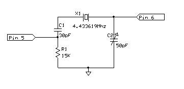
As it is not possible to make the video chip divide the master oscillator by 12 at all times because the division is controlled by the same pin that also controls 50/60 refresh, the solution is to force the CXA1145 into PAL mode at all times, disconnect the oscillator provided by the video chip and provide our own oscillator at the correct PAL colourburst frequency. One nice thing is the CXA1145 has a built in crystal driver so only a few components are required.
As is, this mod will not work on the Megadrive 2. This is because the Megadrive 2's composite encoder does not have a built in crystal driver.
Parts list
- 1x 4.433619Mhz crystal
- 1x 50pF tunable capacitor
- 1x 30pF ceramic capacitor
- 1x 15K resistor
Schematic diagram
Tuning the circuit
The oscillator needs to be fine tuned. This is because TVs are quite sensitive to the colour burst frequency and your frequency will differ depending on the wire lengths used in your circuit. Ideally you would use an oscilloscope or frequency counter for the task but you will get good results manually tuning this circuit if you buy a proper trimmer adjustment tool and have some patience.
Instructions
This section is a little more bare than usual as it is quite simple to do just fiddly at times.
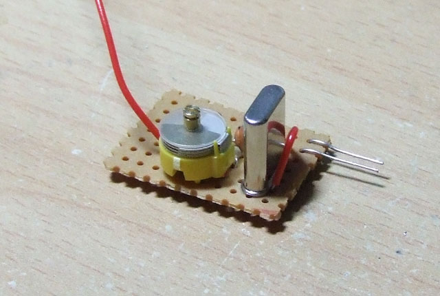
Construct your module according to the schematic. Try to keep wire lengths as short as possible. I find it easier to attach the module if 2 solid metal wires are sticking out (oscillator in/out) as shown in the photo. You'll see why later. The red wire is ground.
Important tips:
- Make sure you use electrical tape to insulate the bottom of your circuit board before fitting it into your Megadrive. You may want to also place some electrical tape on the main board in the Megadrive where the mod will sit for good measure. Failure to do this could be disastrous.
- Keep track and wire lengths short. I suggest taking a track cutter to the strip board once you are finished and cutting away unused portions of track.
Remove the motherboard from your Megadrive and remove the heat sink. Find the CXA1145 and make note of pin 1. Flip the board upside down and mark pin 1 with a permanent marker (so you don't forget). Now you need to cut the trace going to pin 7 carefully. This disables the PAL/NTSC switch. Solder a wire between pin 1 and pin 7 to force the chip into PAL mode at all times. Make sure you really did cut the trace to pin 7 properly. We will be cutting pins 5 and 6 so there is no need to cut traces, but for your information pin 5 is floating and not connected anywhere anyway.
Flip the board the right way up. A suggestion for a close ground - scratch away an area of solder resist for the ground wire in the place shown on the photo. Cut pins 5 and 6 as close as you can to the board and very carefully lift the pins slightly. Do not overdo this or the pins will break off. Bend the metal pins on your module into L shapes and adjust until the module can fit in the gap next to the CXA1145 with the 2 pins touching the correct pins on the CXA1145 like shown. Tin the legs on the CXA1145 and your module, touch together and re-flow to solder in place. Solder the ground lead.
Now all you need to do is connect your Megadrive to your TV with composite and power up your Megadrive with a game in. I strongly suggest clipping a temporary heat sink to both voltage regulators for this next bit as the stock heat sink cannot be used while tuning. Get the game somewhere colourful and pause it. Use a trimmer tool to adjust the variable capacitor and find the range during which you get colour (turn both ways to find the beginning and end). Set the trimmer capacitor roughly in the middle of this range for best results, or tweak as you see fit.
Replace the stock heat sink and put everything back together.


